Circuit Diagram Timer Switch
Circuit off timer switch automatic Simple delay timer circuits explained Digital timer light switch digital timer light switch
555 Delay OFF Timer Circuit For Delay Before Turn OFF Circuit
Timer switch diagram two 12v relay based timer switch circuit using bc547 transistor Timer bathroom
Timer circuit : meter counter circuits :: next.gr
Timer switchCircuit diagram timer switch seekic Timer switch code linkTimer switch circuit diagram.
Schematic timer switch diagram wiringTimer switch circuit diagram Wiring timer elkay columbusElectrical tutorial: timer switch control circuit: timer switch for.

Timer switch
Circuits timer simple circuit delay industrial electronic diagram homemade make build projects solenoid single application chip counter small visit electronicsTimer switch circuit diagram Delay timer circuit off 555 diagram switch power time turn circuits before givenMotion circuit ne555 detector using timer simple diagram projects electronic electronics circuits fig.
Automatic on/off timer switch circuitCircuit diagram timer switch light choose board Timer switchesTimer wiring contactor tether database.

Switch circuit timer electronic seekic motor control
How to build relay timer switchElectronic timer switch circuit How to build a simple industrial delay timer circuitsHow to make a timer switch?.
Simple on delay timer circuit diagram with ic555Timer switch circuit diagram for light Simple motion detector using ne555 timer circuitDigital timer circuit using 555.

An on off switch circuit using a 555 timer with the following diagram
Timer switch touch diagram circuit figEnlarger timer circuit switch off seekic diagram Wiring timer schematic heaterTimer light switch circuit.
Delay circuits wiring alarm sirkuit seconds sequential schematics lebih pressed transistors keterlambatan arduinoTimer switch connection diagram Circuit timer switch relay 12v diagram based bc547 transistor using circuits working volt explanationSimple delay timer circuits explained.

Time switch : working, installation, types, circuit, advantages & its
On delay timer circuit diagram with relay using capacitor️immersion heater timer switch wiring diagram free download| goodimg.co 555 delay off timer circuit for delay before turn off circuitTimer_switch_off_for_enlarger.
Wiring diagram for a timer switchTimer switch light circuit diagram switching minute adjustable control led electronic simple connect ic Delay ic555Touch-free timer switch.

Switch light circuit timer digital yup goes place gr next shem switching
Timer instructablesTouch switch circuit 555 using timer ic simple diagram circuits circuitdigest sensor project electronic digital stable Timer circuit relay switch 555 diagram 741 ic circuits power 12v turn electronic lm741 plug build finder second off minuteTimer circuit switch circuits diagram variable novel gr next timing adjustment addition function general also has.
27 timer switch circuit diagramSwitch wiring connection Simple touch switch circuit using 555 timer ic analog circuitsContactor wiring diagram with timer.

Timer bulb
.
.


Timer switches - Master Electrical

Timer Switch - Electrical - DIY Chatroom Home Improvement Forum
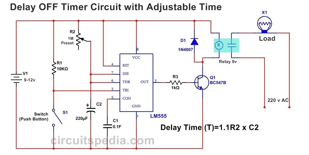
555 Delay OFF Timer Circuit For Delay Before Turn OFF Circuit
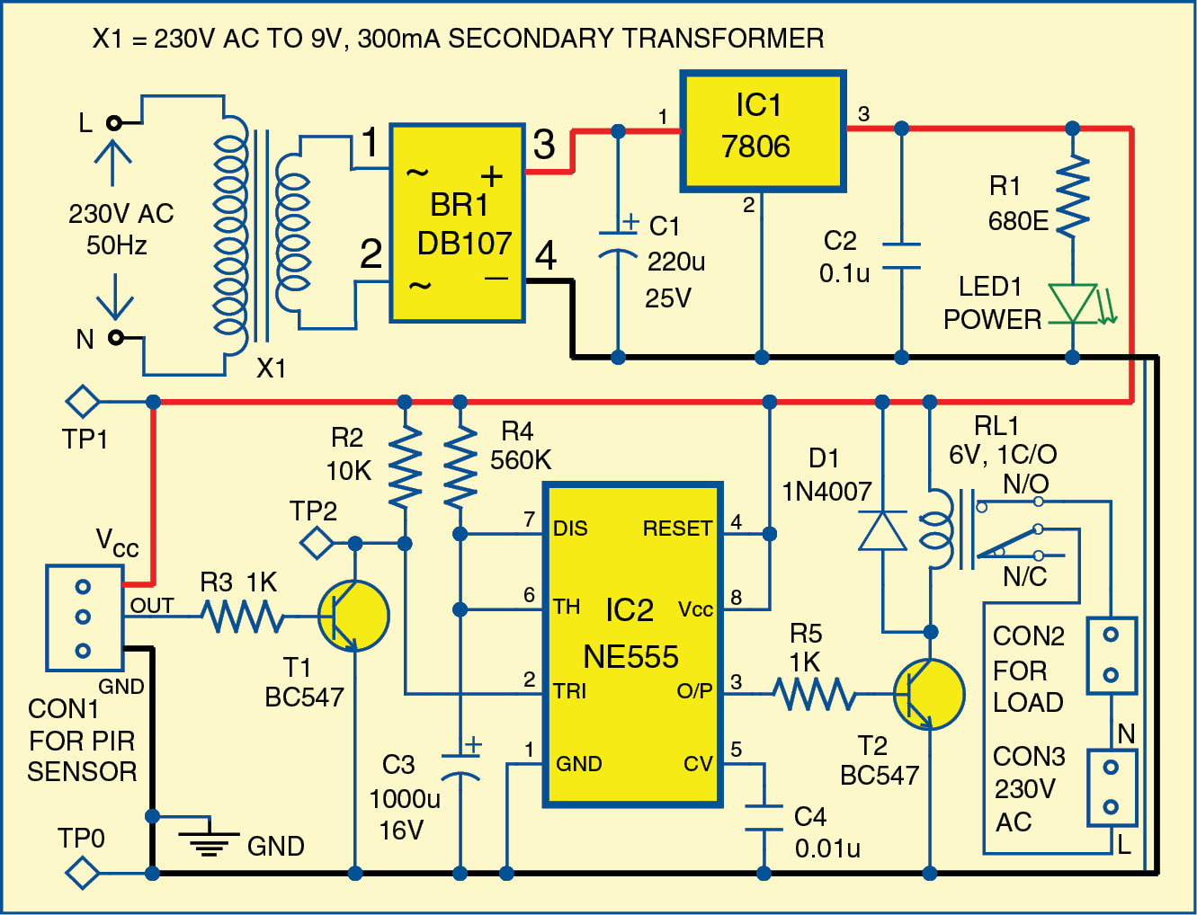
Simple Motion Detector Using NE555 Timer Circuit | Electronic Circuits

How to build Relay Timer switch - circuit diagram