Circuit Diagram Of Decimal Adder
Circuit diagram for 4 bit binary adder using ic 7483 » wiring core Adder in digital electronics, half adder and full adder in digital Adder circuits adders technobyte
4 Bit Binary Subtractor Circuit Diagram - Wiring Diagram and Structur
What is the circuit's logic diagram of a (2-bit binary to decimal How to design half adder and full adder circuits? Common adder circuit diagram
Adder circuits
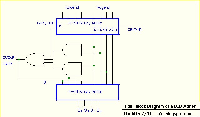
Bcd adder subtractorCircuit diagram of decimal adder Binary decimal bcd coded segment 4511 driver concepts hackaday breadboard 7segment latch protostack microcontrollerFull-adder circuit, the schematic diagram and how it works – deeptronic.
Binary coded decimal or bcd number explained4bit adder to decimal display Adder in digital electronics, half adder and full adder in digitalAdder circuitverse.

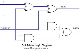
Full adder using two half adders
Decimal or bcd adderAdder decimal circuits 4bit components Adder cmos circuit diagram transistor fa 28t transistors implementation edacafe using transmission gate power fig phdthesis www10 bookFull adder circuit: theory, truth table & construction.
Binary coded decimal adder (4 bit)Adder decimal bit bcd binary coded Adder subtraction circuits4 bit adder subtractor circuit diagram.
Adder circuit combinational half logic
Full adder circuit diagram and truth tableAdder logic half implementation Introduction to full adderElectrical – 4ِ-bit adder in multisim – valuable tech notes.
Adder logic truth gates projectiot123 half sumAdder bcd decimal binary coded digital electronics stage parallel carry digits output next Beginner concepts: binary-coded decimal13+ full adder block diagram.

Adder bcd strange output giving electronics wrong sure did
Binary bcd decimal coded method solutionBcd decimal adder circuit binary javatpoint Adder circuits arithmetic logic diagram meant circuit given belowAdder circuits stld/digital electronics.
Circuit diagram adder common seekicHalf adder circuit diagram Full adder circuit diagramCombinational circuit.

Edacafe: power, accuracy and noise aspects in cmos mixed-signal
4 bit binary subtractor circuit diagramBcd subtractor circuit diagram Adder truth logicDigital electronics: binary coded decimal (bcd) adder.
Circuit diagram of proposed full adderHow to design half adder and full adder circuits? Adder circuit construction binary circuits qiskit sourav guptaAdder block diagram electronics digital half circuit three carry produces receives outputs sum inputs shown below two.
What is meant by arithmetic circuits?
Binary adder and subtraction circuits along with its various typesBcd adder giving strange output? : r/engineeringstudents Adder circuit electronics outputs.
.


4 Bit Binary Subtractor Circuit Diagram - Wiring Diagram and Structur

Decimal or BCD Adder - Javatpoint

How to Design Half Adder and Full Adder Circuits? - EE-Vibes

Full adder using two half adders | Half, Electronics circuit, Full

bcd subtractor circuit diagram - Wiring View and Schematics Diagram

How to Design Half Adder and Full Adder Circuits? - EE-Vibes