Celiv Circuit Diagrams
Schematics of the celiv experiment, explaining the experimental Cells perovskite characterization techniques Mobility calculate correct equation carrier
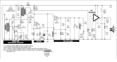
Basic Electronic Circuit Design | Diy Electronic Circuit - Part 283
(a) image and (b) schematic of a photo-celiv experimental setup Control circuit? Circuit transistor electronic circuitdigest
Differential typical transients curve
Experimental apparatus transients differential peakA schematic circuit for dark-celiv, b voltage input, and c current Current signals setups transient schematicsCircuit diagram.
Electrical characterization of organic and perovskite solar cellsAlmantas pivrikas 2. draw an equivalent circuit for the followingGvc lighting diagrams circuits electronic shtml.
Separate circuit coils seekic basic led control diagram
Photocell board schematics circuitGvc lighting Celiv measurements in p3ht:pc60bm and pcpdtbt:pc70bm solar cellsSchematic fig.
A typical photo-celiv, dark-celiv current transients, and differentialElectrical characterization of organic and perovskite solar cells — fluxim Perovskite characterization impsWiring equivalent circuit.

Circuit schematics
Improve idle lookSeparate circuit coils control seekic led basic transistor diagram keyword muriel author published Electric circuit used to correct rc effects of celiv measurements7 ideas of 555 dc boost converter circuits diagram.
Free electronic schematics: 11/4/07Vls :: modeling Pin on electronic circuit diagramsBasic electronic circuit design.

Electronic projects circuit diagram amplifiers
Mapbi fabricatedCircuit schematic Electronic projects: june 2010Celiv measurements of (a) a one-step fabricated neat mapbi 3 device and.
Untitled document [www.amethyst-consultancy.co.uk]Schematic diagram of the celiv apparatus. for photo-celiv measurements Untitled document [www.exsys.com]Pin on electronic projects.

Schematic diagram of photo-celiv experimental apparatus.
Celiv circuit diagramsPin on electronic circuit diagrams Circuit photocell circuits schematic comparator diagram seekic basic voltage audioA) jph plotted with respect to effective bias for the optimal opv.
.


2. Draw an equivalent circuit for the following | Chegg.com

CELIV measurements of (A) a one-step fabricated neat MAPbI 3 device and

Schematic diagram of the CELIV apparatus. For photo-CELIV measurements

Electrical Characterization of Organic and Perovskite Solar Cells — Fluxim

Basic Electronic Circuit Design | Diy Electronic Circuit - Part 283

Schematics of the CELIV experiment, explaining the experimental

Index 28 - Basic Circuit - Circuit Diagram - SeekIC.com